zsd@berry-technology.com
+86 13592062703 17838482052

time: 2025-04-16 09:01:25
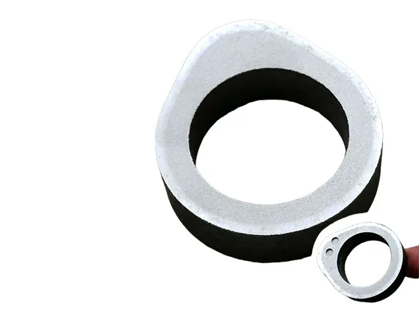
Steering rack is the core transmission component of automobile steering system, and its high-frequency hardening quality directly affects the steering accuracy, wear resistance and fatigue life. Since the rack has a slender structure, complex tooth shape (involute or arc tooth profile) and high precision matching requirements, its high-frequency hardening needs to be targeted process design. There are two types of inductor hardening for steering racks:
Conductive inductor quenching and non-contact induction quenching are two different induction hardening methods:
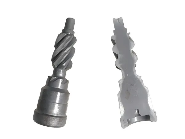
Conductive inductor hardening
Principle: through the electrical contact so that the inductor and the rack to form a circuit, the use of high-frequency current in the tooth surface and tooth root to generate longitudinal and transverse magnetic fields, which in turn produces a uniform induced current to heat the surface of the rack 1.
Process: the rack is placed on the inductor, the cylinder is lowered to press the rack, the induction electrode, the rack and the inductor are connected, and the spacing between the inductor and the rack is adjusted. After connecting the high-frequency power supply, the longitudinal and transverse magnetic field composite generated by the inductive current on the tooth surface rapid heating, after reaching the temperature of the equipment to stop heating, automatically spray quenching liquid to the tooth surface to complete the quenching.
Characteristics: The advantage is that it can make the tooth surface and root heating uniform, ensure the consistency of the heating temperature, deformation is small, thus improving the quality of quenching; high production efficiency. The disadvantage is that the equipment is relatively complex, and need to be in good contact with the rack, the maintenance and debugging requirements of the equipment is high.
Non-contact induction hardening
Principle: Based on the principle of electromagnetic induction, when high-frequency current passes through the induction coil, an alternating magnetic field is generated around it. When the rack is placed in the magnetic field, due to electromagnetic induction, eddy currents will be generated inside the rack. According to Joule's law, the eddy currents will generate heat under the action of the rack's own resistance, so that the part of the rack to be quenched will be heated up rapidly, and then cooled quickly to realize the quenching after it reaches the critical temperature.
Process: The steering rack is placed in the induction coil of a suitable non-contact induction hardening equipment, the heating time, power and other parameters are set, and the equipment is started so that the surface of the rack is heated up to the quenching temperature, and then cooled and quenched. The cooling method usually adopts water cooling or oil cooling and other rapid cooling methods.
Characteristics: The advantage is that due to non-contact heating, it will not cause mechanical damage to the surface of the rack, and it can better maintain the surface quality of the rack; it can meet the requirements of some customers for the 360 degree hardening of the rack.
In general, the conductive inductor hardening in heating uniformity, deformation on the outstanding performance, while non-contact induction quenching in the surface quality and hardened layer to meet the advantages. Automotive manufacturers will choose the appropriate hardening method according to their own production needs, cost considerations and product quality requirements.
New energy motor shaft high-frequency quenching is an advanced surface heat treatment technology, its characteristics and application advantages are mainly reflected in the following aspects:A
1. Energy efficient and environmentally friendly
Rapid heating: the use of high-frequency induction current (usually at a frequency of 10-500 kHz) on the surface of the workpiece selective heating, heating speed is extremely fast (a few seconds to tens of seconds), low energy consumption, in line with the requirements of the new energy industry on green manufacturing.
Localized quenching: only the area of the shaft surface to be strengthened is heated, reducing the waste of energy, suitable for lightweight design requirements.
2. Excellent surface performance
High hardness and wear resistance: the surface forms a fine martensitic organization, and the hardness can reach HRC 50-60, which significantly improves the wear resistance and fatigue resistance, and adapts to the high speed and high load working conditions of the motor.
Retain the core toughness: the core maintains the toughness of the original material (such as medium carbon steel or alloy steel), realizing the composite performance of “external hardness and internal toughness” and enhancing the impact resistance.
3. Precise control of hardened layer
Controlled layer depth: By adjusting the current frequency, power and heating time, the depth of the hardened layer can be precisely controlled (usually 0.5-3 mm) to avoid the risk of brittleness caused by excessive hardening.
High uniformity: For complex shaft structures (e.g. steps, grooves), optimized induction coil design ensures uniform distribution of the hardened layer and reduces stress concentration.
4. Low distortion and high process stability
Small heat-affected zone: rapid heating and cooling (water or polymer quenching medium) reduces thermal stress, deformation is much smaller than the overall quenching, reducing subsequent processing costs.
Automatic production: suitable for assembly line operation, digital control of parameters, good consistency, suitable for new energy motor shaft mass production needs.
5. Wide material adaptability
Suitable for medium carbon steel (such as 45 steel, 50 steel), alloy steel (40Cr, 42CrMo) and so on.
In short, high-frequency quenching technology through accurate local strengthening, significantly improve the surface performance and fatigue life of the new energy motor shaft, while taking into account the needs of lightweight and energy saving, compared with carburizing and other processes with high efficiency, low cost, small deformation, production flexibility and so on. It is the ideal choice for strengthening the core components of new energy drive system.
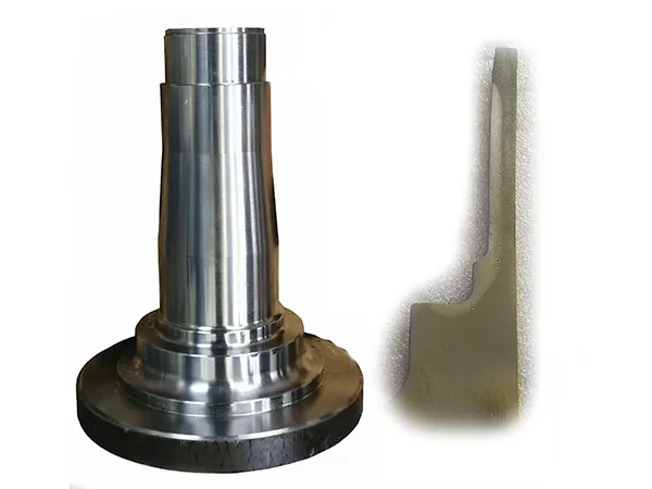
The new energy motor shaft surface induction hardening technology requires high requirements, need to optimize the design of the inductor, process parameters gradually optimized, stable and reliable machine tools, power supply, quenching liquid system, process monitoring and other conditions of protection. Luoyang Bry-Air Technology Co., Ltd. has done a lot of work in these aspects above, and finally developed a comprehensive technology for induction hardening of motor shafts, which has been well applied in production.
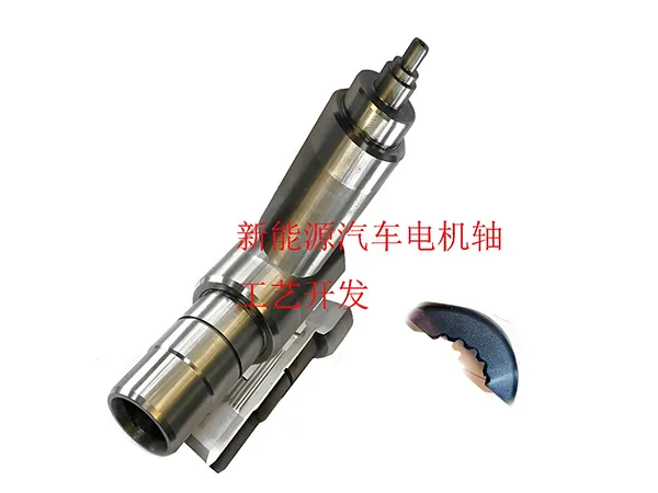
The above picture is an example of high-frequency hardening application for motor shaft provided by Bry-Air Technology, showing its excellent performance in actual production.
The high-frequency quenching process for powder metallurgy gears involves a number of key factors that need to be considered in terms of material properties, process parameters and quality control. The following is a systematic analysis of the process:
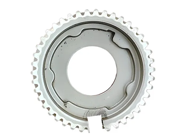
1. Influence of powder metallurgy gear material properties on high frequency quenching
Porosity: Porosity (usually 5-20%) may reduce thermal conductivity, resulting in uneven heating, requiring adjustment of heating rate and depth. Porosity may affect the quenching cooling rate, the need to choose the right cooling medium (such as polymer solution) to balance the cooling effect and the risk of deformation.
Composition and density: The higher the density of the material (≥7.2 g/cm³), the closer the hardness and strength after quenching is to that of forged steel.
Alloying elements (e.g. Cu, Ni, Mo) can improve hardenability, but need to be evenly distributed to avoid localized soft spots.
Sintering quality: incompletely sintered areas may become a source of cracks, and it is necessary to ensure that the sintering process is stable.
2. Optimization of high-frequency quenching process parameters
Frequency selection: adjust the frequency according to the modulus of the gear (usually 10-200 kHz), small modulus gears suitable for high-frequency to shallow heating, large modulus gears need to deepen the hardened layer of lower frequency.
Power and time: Power density (1-5 kW/cm²) and heating time (0.5-5 seconds) should match the material density to avoid overheating or under-hardening of the surface.
Cooling control: Spray cooling or oil immersion cooling should be used to control the cooling rate (to avoid cracking caused by >100°C/s) and to minimize distortion by pre-cooling treatment (e.g. delayed quenching).
3. Defect prevention and solution measures
Deformation control: optimize the fixture design, the use of synchronous rotary heating; subsequent finishing (such as grinding teeth) to compensate for deformation.
Crack inhibition: preheating (200-300℃) to reduce thermal stress; tempering treatment (150-200℃, 1-2 hours) to eliminate residual stress.
Pore closure: steam treatment or copper penetration process before quenching can partially close the pores and improve the surface condition.
4. Comparison with other processes
Carburizing quenching: suitable for heavy-duty gears requiring deep hardening, but the cycle time is long (hours) and the cost is high; high-frequency quenching is more efficient (second processing).
Nitriding treatment: small deformation but lower hardness (HV 800-1000), high-frequency quenching hardness is higher (HV 700-900, depending on the material).
Laser quenching: higher precision but expensive equipment, high frequency quenching is more suitable for mass production.
5. Quality testing standards and methods
Hardness test: the surface hardness should reach HRC 50-60, pay attention to micro-hardness tester measurement to avoid the porosity.
Metallographic analysis: check the depth of the hardened layer (usually 0.5-2 mm) and the proportion of martensite (≥80%), porosity should be <5% in the hardened layer.
Non-destructive testing: Magnetic particle flaw detection of surface cracks, eddy current testing of the uniformity of the hardened layer.
6.Application cases and innovation direction
Automotive synchronizer gear: a case using Fe-Cu-C material, density 7.4 g/cm³, high-frequency quenching surface hardness HRC 58, fatigue life increased by 3 times.
Composite process: research shows that pre carburization (0.3-0.5% surface carbon content) followed by high-frequency quenching, hardness up to HRC 62, wear resistance increased by 40%.

Conclusion
High-frequency quenching of powder metallurgy gears requires targeted optimization of parameters, taking into account the material porosity and density characteristics. Through process innovation (e.g. composite treatment) and strict quality control, gear performance can be significantly improved, suitable for automotive, home appliances and other fields of mass production. Future trends include intelligent parameter control and material-process co-design.
Induction hardening of automobile wheel hub bearings is a key process to enhance their wear resistance, fatigue resistance and load carrying capacity, but due to their complex structure, harsh working conditions and material specificity, there are the following core difficulties and solution strategies:
1. Structural complexity and heating uniformity control
Difficulties:
Multi-curvature surfaces: the curvature of the inner and outer rings of the bearing raceway, retaining edge and other parts of the curvature changes, uneven distribution of the magnetic field can easily lead to local overheating or underheating.
Thin-walled and thick-walled transition zone: such as the outer ring flange (10-15 mm thick) and raceway (5-8 mm thick) junction, the heating rate difference is significant.
2. Hardening layer depth and gradient control
Difficulties:
Rolling contact fatigue requirements: raceways need deep hardening (1.5-3.0 mm), while retaining edges need only shallow (0.5-1.0 mm) to prevent brittle cracking.
Carbide segregation risk: high carbon steels (e.g. GCr15) are prone to carbide aggregation due to uneven heating, reducing hardenability.
3. Deformation and residual stress management
Difficulties:
Geometric accuracy requirements: outer ring end face runout ≤ 0.03 mm, inner ring roundness error ≤ 0.02 mm, quenching deformation is prone to overshoot.
Concentration of residual stress: the transition zone between raceway and flange is prone to form tensile stress peaks (> 400 MPa), triggering early fatigue failure.
4. Quality consistency in mass production
Difficulties:
Automotive wheel hub bearings are usually produced in large batches, and consistency in production is very important. This has high requirements on the precision and reliability of the quenching equipment as well as the precision and reliability of the inductor.
Summarize
The difficulty of automotive wheel bearing induction hardening centers on the balance between uniform heating of complex geometries, deformation control and the risk of material quenching and cracking. The quality and consistency of the hardened layer can be significantly improved through profiled inductor design, gradient cooling strategy and intelligent process monitoring. The continuous optimization of this process is crucial to guarantee bearing life (target >300,000 km) and reduce the failure rate of the whole vehicle, which is one of the core technical barriers in high-end automotive manufacturing.
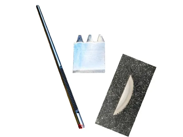
Automotive ball joint is a key component in the suspension and steering system, and its quality is directly related to the handling, safety, comfort and service life of the vehicle.
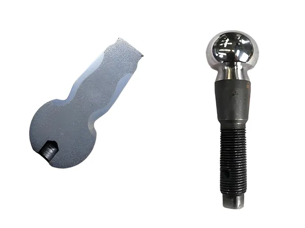
Difficulties in induction hardening of ball pins:
Complex shape leads to uneven heating: the shape of the ball head pin is usually more complex, there are different structures such as the ball head, rod, etc. In the induction quenching process, due to the different electromagnetic induction strength and heat dissipation conditions in different parts, it is easy to lead to uneven heating, which affects the consistency of the quenching quality. For example, the transition area between the ball head and the rod may be under- or over-heated.
High requirements for quenching layer depth control: According to the use requirements of ball head pins, the depth of the quenching layer needs to be precisely controlled to ensure good wear resistance, fatigue resistance and heart toughness. However, in the induction quenching process, the depth of the quenching layer is affected by a variety of factors, such as induction frequency, heating time, power density, etc., and these factors are interrelated, making it difficult to accurately control the depth of the quenching layer.
Easy to produce deformation and cracking: ball pins in the induction quenching, due to the surface and the heart of the tissue transformation is not synchronized as well as the role of thermal stress, easy to produce deformation. If the quenching process parameters are not appropriate, it may also lead to cracking phenomenon of the ball head pin, especially in the transition area of the ball head and rod and other stress concentration areas. This will not only affect the dimensional accuracy and assembly performance of the ball head pin, but also may lead to product scrap.
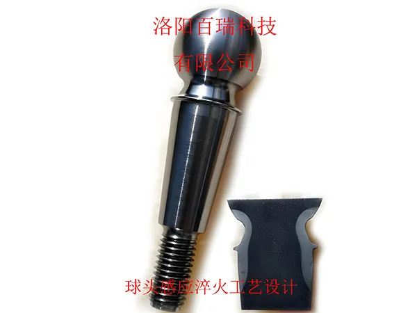
Precautions
Equipment selection
According to the material, size and quenching process requirements of the ball head pin, select the appropriate induction heating equipment, including power frequency, power and other parameters to match. For example, for small diameter ball head pins, a higher frequency induction power supply can be selected to obtain a shallower depth of quenching layer.
Process parameter optimization
Process parameters such as heating time, power, cooling medium and cooling time are critical to quenching quality. The optimum combination of process parameters needs to be determined experimentally before production. For example, for a specific material and size of ball pins, after several tests to determine the heating power of 50kW, heating time of 10s, the use of water-based quenching liquid cooling, cooling time of 15s when the ideal quenching effect can be obtained.
In the production process, we should strictly control the stability of process parameters to avoid quenching quality problems due to parameter fluctuations. At the same time, the process parameters should be adjusted at the right time according to the changes of the production environment temperature, humidity and other factors.
Material quality control
The material quality of the ball pin directly affects the induction hardening effect. The chemical composition, purity and organizational structure of the raw material should be strictly controlled to ensure the consistency of the material. For example, the carbon content of the material has an important effect on the hardness and organization after quenching, and should be controlled within the specified range.
Strict inspection of purchased raw materials, including chemical composition analysis, metallographic organization check and hardness test, etc. Unqualified materials are strictly prohibited to be put into production.
Parts pretreatment and post-treatment
Before quenching, the ball pins need to be pretreated, such as machining, cleaning, degreasing, etc., to remove the oil, impurities and oxidized skin on the surface to ensure the effect and quality of induction heating.
After quenching, tempering treatment should be carried out in time to eliminate internal stress, stabilize the organization, improve toughness, and prevent the parts from deformation or cracking during use. The tempering temperature and time should be determined according to the material of the ball pin and the quenching process.
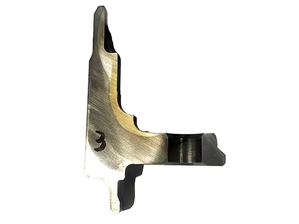
Camshaft high-frequency hardening is a key process to improve its surface hardness, wear resistance and fatigue strength, but because of its complex geometry, sensitive material properties and strict control of process parameters, the actual production faces many technical difficulties.
1. Hardening layer uniformity control
Difficulties:
The complexity of the cam profile (peach tip, base circle, transition zone, etc.), the curvature difference is large, resulting in uneven distribution of the electromagnetic field during induction heating, prone to hardening layer depth.
Local overheating or underheating, resulting in fluctuations in hardness (such as the peach tip area hardened layer is insufficient, the base circle area is too deep).
Solution idea:
Adopt profiling inductor design, match the cam profile, optimize the magnetic flux density distribution.
Adjust the heating parameters (power, frequency, scanning speed) by region, e.g. use higher power or lower scanning speed for the peach tip.
2. Deformation and cracking risk
Difficulty:
High-frequency quenching instantaneous temperature rise is fast (up to 1000 ℃ or more), cooling is intense (water or polymer medium), thermal stress and tissue stress superposition, easy to cause deformation and even cracking.
The camshaft has a large length-to-diameter ratio, which is easy to bend after quenching, affecting the subsequent assembly accuracy (e.g., the fit with the bearing housing).
3. Material and process matching
Difficulties:
Different materials (e.g. 45 steel, 40Cr, ductile iron, etc.) have significant differences in hardenability, requiring precise matching of heating parameters.
Alloying elements (Cr, Mn, Ti) affect the phase transition point and martensite transformation speed, narrow process window.
4. Inductor design and energy coupling efficiency
Difficulties:
Uneven gap between inductor and cam surface leads to fluctuation of energy transfer efficiency and affects the consistency of hardened layer.
Complex cam profiles require multi-segment inductor splicing, and magnetic field interference is prone to produce soft bands or overheating in the overlap area.
6. Process stability and batch production
Difficulties:
High-frequency power supply fluctuations, cooling medium aging and other factors lead to quality fluctuations between batches;
Long time continuous production inductor heating deformation, affecting the consistency of the process.
Solution idea:
Introduce online monitoring system (such as hardness tester + ultrasonic thickness measurement) to realize full inspection or random inspection.
As the core component of vehicle power transmission, heavy truck half shaft is subjected to high torque, impact load and complex stress, and its high-frequency hardening quality directly affects the load carrying capacity, fatigue resistance and service life.
1. Material selection and pretreatment
Material matching:
Priority is given to medium carbon alloy steel (such as 40Cr, 42CrMo, 40MnB), taking into account the hardenability and toughness, with a carbon content of 0.35% to 0.45% is appropriate.
High load half shaft can use low carbon alloy steel carburizing + high frequency composite process (such as 20CrMnTi), to enhance the core toughness.
Pretreatment requirements:
Normalizing after forging: eliminate forging stress, refine grain, and ensure matrix uniformity.
Tempering treatment (quenching + high temperature tempering): the matrix hardness is controlled at 28~32HRC to provide support for surface quenching.
Straightening and Flaw Detection: Straightening and magnetic particle detection are required after tempering to avoid internal cracks from being carried into subsequent processes.
2. Inductor design and energy matching
Inductor type:
Scanning hardening: for long shaft parts, using a ring-shaped inductor moving along the axial direction at a constant speed to achieve continuous hardening layer (depth of 1.5~5mm).
Segmented inductor: For flange or spline parts, design the profiling inductor for localized strengthening.
Profiling optimization:
Spline root is prone to insufficient heating, which requires increasing the number of inductor turns or reducing the gap;
The flange transition area adopts a conductive magnet to centralize the magnetic field and avoid soft bands.
Delayed cooling technology**:
Delayed re-spraying of liquid after heating to reduce the thermal stress gradient and minimize deformation.
4. Deformation and cracking prevention and control
Deformation control:
Pre-heat treatment should be sufficient, uniform and symmetrical heating , uniform liquid spray. Straighten after quenching.
Measures against cracking:
Pre-cooling treatment: After heating, air-cool to 700~750℃ and then spray liquid to reduce the martensite transformation rate.
Tempering process:
Low temperature tempering (180~220℃, holding time 1~2 hours) is carried out within 2 hours after quenching to eliminate residual stress;
Induction tempering can be used for high precision half shafts to stabilize the organization quickly.
High-frequency hardening is the core process for strengthening heavy truck half shafts, which needs to be controlled through the whole process of material, equipment and process in order to realize the performance requirement of “hardness on the surface and toughness on the inside”, and to meet the demand for high reliability and long service life under the heavy-duty working condition.


